Larry Troyer, Duncan Aviation Avionics Instrument Tech Rep, troublshoots the two most common causes of APS-80 Autopilot System failure.
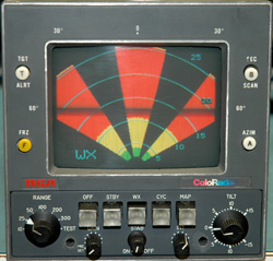
The autopilot / flight director system is a complicated system that is common in aircraft from light twins to corporate jets.
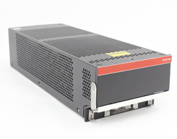
- FGC-80- (Flight Director)
- APC-80
- APA-80
The FGC-80- (Flight Director) processes all lateral/vertical signal inputs depending on the selected mode. It controls the position of the command bars in the Flight Directory Indicator and sends commands to the APC-80. APC-80 receives and processes commands from the Flight Director computer and passes them on to the APA-80, which drives the individual servo motors to control aircraft flight.
Two Most Common Failures
1. Autopilot intermittently disengages during flight
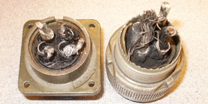
Most likely cause is the APC or APA. These computers have multiple internal dc power supplies that tend to get out of tolerance or fail completely. They can be temperature sensitive (hot or cold) failing at one specific temperature.
Troubleshooting:
- If you are able to duplicate the discrepancy on the ground, it is possible to isolate the faulty computer by heating or cooling each box individually.
- Engage the autopilot on the ground and manually override the controls in pitch or roll. If the autopilot disconnects, the most likely cause is in the APA due to faulty torque monitors.
2. Autopilot will not engage
Troubleshooting:
When the autopilot won't engage, the APA and APC is still most likely the cause. However because of the extensive internal computer monitoring, there are many other things that could be contributing to the failure. When activating the lever to engage the autopilot, the system automatically initiates a self-test routine. During this self-test a dc voltage is sent to the two NAC-80 accelerometers that in turn generate a fixed signal back to the APA. A correct signal is required to successfully pass the self-test. The NAC-80s also put out a valid flag which is monitored in the APP-80 control head as a condition for engagement.
Other conditions required before the autopilot will engage:
- Valid vertical gyro
- Valid from the yaw damper computer
- Correct part number status on both computers (APA & APC)
- Continuity thru the yoke disconnect switch
If you have access to a breakout box or logic monitor it helps to isolate the problem down to a box or aircraft problem. Other wise the majority of the times engage problems are caused by either the APC-80 or the APA-80 computers.
More Autopilot Squawk Solutions on the Duncan Download