banner1.jpg

The Duncan Download Blog: Business Aviation Advice & Observations

Challenger 604 MLG Main Fitting Bushing Improvement

Posted by Diane Heiserman on Wed, Dec 19, 2012 @ 04:15 PM

Jerry Cable, Accessory Tech Rep

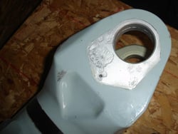
Corrosion on the MLG casing.

Corrosion on the MLG casing.

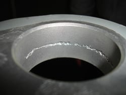
Corrosion in the pintle pin bushing boss of the MLG casing.

Corrosion in the pintle pin bushing boss of the MLG casing.

Messier is aware that the current configuration and greasing procedure of the main landing gear (MLG) main fitting may not allow grease to be forced into the joint between the MLG main fitting and trailing link assembly. The lack of grease on these parts can lead to abnormal and excessive wear on the bushings. A supplemental greasing procedure and associated tooling has been developed by Messier to lubricate this joint. The procedure will allow grease to reach the affected areas, but is somewhat cumbersome to perform.

Bushing Design Improvements

Messier and Bombardier are in the process of releasing Service Bulletins that improve the bushing design to eliminate the need for a supplemental greasing procedure. It is recommended that this improvement be installed during the next 96-month or 192-month inspection interval.

The improvement not only rectifies the problem of grease passage to the proper area but also implements a new installation procedure. The installation procedure, which uses wet sealant on all areas of the bushings, will help to alleviate the corrosion problem present on many of the main fittings under the bushings.

While the bulletins have not yet been released, the improvements can be implemented and approved through a Messier concession and subsequent Bombardier SRPSA approval. Consider these improvements and the next scheduled inspection to prevent further or future problems with the MLG that could lead to costly repairs or even more costly replacement. Contact Duncan Aviation's landing gear experts for more information. 

Jerry Cable is an Accessories Tech Rep located at Duncan Aviation’s Lincoln, Nebr., facility. He is a landing gear and accessory components and systems specialist. His aviation career began in 1991.

Tags: Parts & Accessories, Troubleshooting, Landing Gear

Learjet Aircraft: Troubleshooting the Master Caution Box

Posted by Diane Heiserman on Mon, Dec 03, 2012 @ 10:01 AM

Contributed by Jerry Cable, Accessory Tech Rep

Master Caution Box

Master Caution Box, P/N 2618055-29, repaired and returned to service by Duncan Aviation electrical technicians.

The Learjet 35/36 model and some Learjet 20s are wired in such a manner that there is potential to cause problems with the Master Caution Box (MCB), P/N 2610855-29 and 2618055-30, which may result in incorrect troubleshooting of the MCB and Glare Shield. It could also result in complete failure of the MCB.

For example: three Transistors (Q210, Q211 and Q212) are mounted in the nose of the aircraft. Transistors Q210 and Q212 control light intensity of the Pilot and Copilot Glare Shield assembly. Transistor Q211 is for a 3.4Vdc regulated voltage Power Supply for the Master Caution Box; that supplies power to the Electronic Integrated Circuit (IC) inside the MCB. The ICs are voltage sensitive with a maximum rating of 15 Volts direct current (Vdc). If transistor Q211 fails, the voltage will be driven to 28 Vdc, nearly twice the maximum voltage that the ICs can handle. This can result in the failure ICs in the MCB.

Care should be taken when installing the new MCB to ensure that unregulated voltage (above 5Vdc) is not applied to the MCB (failed Q211); causing a complete failure of the new MCB. Prior to replacing the MCB; Q211, insulator and hardware should be checked or replaced.

If in doubt, these transistors are easy to access and cheap enough to warrant changing them at regular intervals.

Recommended procedures when replacing or troubleshooting the MCB

  1. Check the GROUND leads from the master caution connectors to aircraft ground. This is to insure Master Caution Box has proper grounding. Problems caused by grounding issues can be numerous; from completely inoperative and intermittent to erroneous caution trips. Troubleshooting this problem can be a daunting task but will save time and money in the long run.
  2. Verify TRANSISTOR Q211 is working properly and replace if needed. A failure of this transistor will allow the unregulated voltage to be applied to the MCB, leading to a complete failure when power is applied to the aircraft.

For exact details including “pin outs,” connectors, meter readings, etc.; contact Duncan Aviation’s Accessory Electrical Team Leader Tim Smith.

Now through the end of January 2013, save $100 on your next repair, overhaul or functional test on your electrical and pneumatic units. Download the details and coupon here

Jerry Cable is an Accessories Tech Rep located at Duncan Aviation’s Lincoln, Nebr., facility. He is a landing gear and accessory components and systems specialist. His aviation career began in 1991.

Tags: Parts & Accessories, Troubleshooting, Learjet

Hawker 800XP: Troubleshooting HF Systems Squawks

Posted by Diane Heiserman on Tue, Nov 20, 2012 @ 02:15 PM

Contributed by Scott McKenzie, Avionics Tech Rep

Hawker 800XP

If your Hawker 800XP's HF system is showing signs of intermittent faults, the solution may be as simple as checking for proper bonding at the antenna and antenna coupler.

A Hawker 800XP operator, who was experiencing a squawk on both #1 and #2 HF systems, recently contacted us for support. He was not able to receive transmissions on either system.

Since both systems were exhibiting the same symptoms, the obvious place to begin troubleshooting is by focusing on components that are common between the #1 and #2 HF systems. In this instance: the dual KHF-950 HF system with a shunt antenna. The common components are the KA 162 Dual External Capacitor (or KA 160 Dual Antenna Adapter, if it is a long wire antenna installation) and the HF antenna itself.

Proper Antenna Bonding

The function of the KA 162 Dual External Capacitor is to connect the antenna to the active antenna coupler. Since the HF antenna in this installation is essentially the vertical stabilizer leading edge, the one thing to check with the antenna is proper bonding. Good bonding of the antenna, KAC 952 Power Amplifier/Antenna Coupler and KA 161 External Capacitor or KA 162 Dual Antenna Capacitor is essential for proper operation of the HF system. I cannot count the number of HF squawks that have been remedied by Duncan Aviation avionics technicians simply by going through and cleaning corroded bonding connections at the antenna or antenna coupler.

Tuning faults are also a common squawk for HF systems that have corroded or poor bonding at the antenna or antenna coupler. Bonding at the antenna coupler is done with a bonding strap, and the resistance should not exceed .003 ohms.

So if your aircraft's HF system begins to show signs of intermittent faults, take a few minutes to first check for proper bonding at the antenna and antenna coupler. Many times, this can remedy the problem and save you time and money in the process.

Duncan Aviation is still a Hawker Service Center

In light of the recent changes in the industry for Hawker operators, I want to remind you that Duncan Aviation continues to provide comprehensive Hawker aircraft service and support at all Duncan locations around the world. We are an industry leader in Hawker maintenance, structural repair, landing gear/component overhauls, engine MPIs, avionics upgrades, paint and interior. Our experience and capabilities are second to none.

For more information about Duncan Aviation’s Hawker Services, contact any one of the many Duncan Aviation Hawker experts.

If you have any questions or need assistance when troubleshooting a KHF-950 HF system, contact Duncan Aviation's Avionics Tech Reps, available 24 hours a day, every day.

 Avionics Tech Reps

Scott McKenzie is an avionics tech rep located in Duncan Aviation's Lincoln, Nebraska, facility. He specializes in troubleshooting the latest in avionics systems installed on aircraft today. His aviation career began in 1995.

Tags: Avionics & Instruments, Squawk Solution, Troubleshooting, Hawker

The Pitfalls of Ignoring Bleed Air Leaks on your Business Aircraft

Posted by Diane Heiserman on Tue, Nov 13, 2012 @ 01:44 PM

Contributed by Jerry Cable, Accessory Tech Rep

Small leaks become big problem

Several small leaks in the bleed air system of your business aircraft can add up to a significant problem.

Inherent with most business aircraft is the need to utilize engine bleed air. Whether it be for de-icing, cabin heat or system control; bleed air is vital to the aircraft operation. Leaks in the bleed air system are common and often neglected for one reason or another, but one thing is for certain; a leak never fixes itself.

High Bleed Air System Demands

While a small leak in the bleed air system is usually not a problem and is probably the reason we neglect fixing it; several small leaks can be a significant problem. The system has several components which control the volume and temperature of the air in different sections of the aircraft and these components self-regulate based on the demand for that air.

Unnecessary Removal of Suspect Components

The cabin may be in demand for warm air, the windshield needs defogged and the leading edges need de-iced. The demand for bleed air begins to climb, yet the cabin is still cold. This might lead to inadvertently removing suspected components, such as the cabin temperature controller or modulating valve, for repair. Sure they may need a reseal but the real problem lies in the leaks. The system is demanding more than what the system can supply due to the leaks.

Erroneous Temperature Sensor Readings

There are other situations where a bleed air leak could cause even more confusion. A bleed air leak in the area of a temperature sensor can cause erroneous readings. For example, if hot bleed air leaks next to an air-conditioning or de-ice temp senor, it can cause them to read temperatures not accurate to the duct they are installed in.

To avoid the unnecessary removal of components and ease in the trouble shooting process, it is always a good idea to spend the necessary time to fix the bleed air leaks when they are small. It may not seem like a big leak but every little bit helps.

For help in identifying, troubleshooting and fixing blead air leaks, contact Jerry Cable, Duncan Aviation's Accessory Tech Rep.

Now through the end of January 2013, save $100 on your next repair, overhaul or functional test on your electrical and pneumatic units. Download the details and coupon here

Jerry Cable is an Accessories Tech Rep located at Duncan Aviation’s Lincoln, Nebr., facility. He is a landing gear and accessory components and systems specialist. His aviation career began in 1991.

Tags: Parts & Accessories, Troubleshooting

Squawk Solution: Proper Operation of the KHF-950 HF System

Posted by Diane Heiserman on Thu, Sep 27, 2012 @ 01:00 PM

Contributed by Scott McKenzie, Avionics Tech Rep

At Duncan Aviation, we recently have had a number of components sent in for a KHF-950 HF system, with a KFS-594 Miniature Control Unit installed, that have been squawked as being stuck in transmit mode or the frequency is changing on the controller every time a transmit is attempted. After bench testing, it was determined that there were no faults with the suspected units, but a misunderstanding of the proper operation of this system. 

Here’s a quick refresher course.

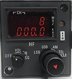
Direct Frequency Mode

figure 1. Direct Frequency Mode.

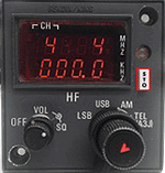
Channel Mode

figure 2. Channel Mode.

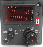
Program Mode

figure 3. Program Mode.

Direct Frequency Mode

The first thing that technicians should do when testing the KHF-950 HF system is select channel 0 (direct frequency mode) on the HF controller and enter the desired frequency.  (figure 1. Direct Frequency Mode)

This ensures the frequency that is selected via the controller is the frequency that will be both received and transmitted (simplex operation) on when the microphone is keyed. If any other channel is selected (1 through 19), it is possible that the frequency displayed on the controller will change when attempting to transmit. 

 Channel Mode

By selecting a channel (1 through 19), the user can store preset frequencies using the white STO button. To program a preset channel frequency, first select the channel. Next, enter the desired frequency and press the STO button. (figure 2. Channel Mode)

Program Mode

Each channel can also be programmed for duplex operation. Duplex operation is receiving on one frequency, while transmitting on a different frequency. To program a channel for duplex operation, first select the desired channel, then enter the desired receive frequency and press the STO button. The display on the control should now be in program mode. Program mode is annunciated by a flashing dash in the space adjacent to the channel number. (figure 3. Program Mode photo)

Also note that the TX annunciation is in the upper right hand corner. You may now enter the desired transmit frequency, and press the STO button again. The selected channel is now programmed for duplex operation.

STO Button

The STO button can perform a couple of other functions in addition to being used to store preset frequencies. If the STO button pressed while the microphone is keyed, a 1000Hz tone will be transmitted. This is used to break the squelch of some stations. 

Also, pressing the STO button will clear any error conditions, which are annunciated by a flashing "E" being displayed for more than three seconds. If the display shows a TX annunciation upon power up, and you are not able to control the cursor, pressing the STO button three times should clear this indication and allow for full function of the HF controller.

If you have any questions or need assistance when troubleshooting a KHF-950 HF system, contact Duncan Aviation's Avionics Tech Reps, available 24 hours a day, every day.

 Avionics Tech Reps

Scott McKenzie is an avionics tech rep located in Duncan Aviation's Lincoln, Nebraska, facility. He specializes in troubleshooting the latest in avionics systems installed on aircraft today. His aviation career began in 1995.

Tags: Avionics & Instruments, Squawk Solution, Troubleshooting

Honeywell RNZ-850/851 Avionics AD Deadline Approaching

Posted by Diane Heiserman on Tue, Sep 25, 2012 @ 09:00 AM

Contributed by Scott McKenzie, Avionics Tech Rep

The date for complying with Airworthiness Directive (AD) 2010-07-02 is rapidly approaching. November 3, 2012 is the date that operators are required to be in compliance of this AD. The AD is applicable to Honeywell RNZ-850/851 Integrated Navigation Units and addresses possible erroneous glide slope or localizer display indications.

Does this AD apply to you?

Verifying applicability is a simple two-step process.

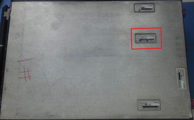
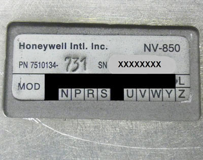
NV-850 module data plateStep 1 NV-850 module data tag mod status Step 2
  1. Check the NV-850 module data plate on the bottom of the RNZ-850/851 Integrated Navigation Unit. This AD is only applicable to units with NV-850 modules with the following part numbers: 7510134-611, -631, -701, -731, -811, -831, -901 or -931.
  2. If you have a unit installed with one of the above part numbers, check the mod status on the bottom of the data tag. If the unit has block “T” blackened out, then the unit IS in compliance of AD2010-07-02. If the unit does not have mod “T” installed, then the unit requires modification to comply with this AD.

Don’t wait until the last minute to take care of this AD. Demand for this modification will only get higher. The longer you wait to comply, the longer you may wait to get your unit back. Duncan Aviation is able to perform the modification necessary to comply with AD2010-07-02. Contact a Duncan Aviation Avionics Tech Rep for more information.

Avionics Tech Reps

Scott McKenzie is an avionics tech rep located in Duncan Aviation's Lincoln, Nebraska, facility. He specializes in troubleshooting the latest in avionics systems installed on aircraft today. His aviation career began in 1995.

Tags: Avionics & Instruments, Troubleshooting

The Trouble With Troubleshooting Avionics Squawks

Posted by Diane Heiserman on Tue, Jun 26, 2012 @ 08:00 AM

Contributed by Curt Campbell, Avionics Tech Rep

Chain of communication

Long chains of communication are notorious for 'losing' pertinent information about a squawk.

Remember the “telephone” game when you were a kid? The game where a specific sentence or phrase was whispered to the first person in line and they in turn whispered it to the next and the next, until it got to the last person? Most of the time what the last person heard is nowhere near the original phrase.

Although we may be grown up, we still have similar issues with long chains of communication. In my experience as an Avionics Tech Rep, unless I am talking to the person who witnessed the squawk, I go under the assumption that there is always more to the story than what I am told. Or in some cases, a completely different story altogether.

During a squawk event, the first opportunity for ‘lost’ salient information is with the flight crew. They are tasked with the verbalization of the squawk, and in an effort to be concise, may inadvertently leave out valuable clues that will help pinpoint the cause of the event. They may also be unaware of additional checks or other observations that can aid in troubleshooting. Of course every time the crew’s information is passed on to the Director of Maintenance (DOM), MRO or avionics tech rep, the verbiage is subtlety changed based on the perceptions of each individual, resulting in what in some cases is a completely different squawk than what was originally witnessed. This results in misdiagnosis, expensive parts needlessly changed and lengthy intervals to finally diagnose and clear the discrepancy.

How can you avoid this wasted time and extra expense? Here are some simple tips that can save you in the long-run.

Eliminate the Middleman

llow the person or team charged with resolution of the issue direct access to the crew member who witnessed the issue. Don’t assume you know what the crew saw. Their perceptions may be different than yours

Use That Smartphone as a Troubleshooting Aid

If the issue is visual, take a video of the failure. This is particularly helpful for flight control system problems, which can be difficult to describe accurately. In the case of the flight control system, try to capture the primary flight instruments as well as the yoke movements in the video. 

Educate Your Crew

Make sure the crew understands common troubleshooting steps for the specific systems installed in your aircraft. For instance, I often find the crew will observe a flight control system issue at cruise with altitude hold and GPS modes selected, but will not try other modes such as HDG and Pitch hold. Testing these modes at the time the squawk occurs would significantly reduce the required troubleshooting and/or unnecessary parts procurement.

Intermittent & Ongoing Squawks

Send the crew off with a checklist of things to accomplish when the issue occurs. Conditions such as altitude, airspeed, temperature, weather conditions, can all play a roll in determination of the issue.

Call Your MRO Inflight

I’ve participated in ‘live troubleshooting’ calls many times and it works. They can ask questions in real-time, often resulting in quicker diagnosis and faster repair.

Duncan Aviation has twenty Technical Representatives, available 24 hours a day, seven days a week, to troubleshoot and answer questions about every aircraft, engine and avionics system in a business aircraft. They are proactive in their education, taking the necessary steps to stay current on the latest technologies. They spend hours researching the latest Airworthiness Directives (AD), Service Bulletins (SB) and Service Letters (SL) released by the Original Equipment Manufacturers (OEMs) and impart that knowledge to technicians and customers.

Curt Campbell is a Duncan Aviation Avionics Tech Rep. located in Lincoln, NE, specializing in troubleshooting squawks and offering tech support for business aircraft avionics. Curt's aviation career began in 1975.
Tags: Avionics & Instruments, Troubleshooting

Troubleshooting Autopilot-Induced Control Surface Oscillations

Posted by Diane Heiserman on Mon, Feb 06, 2012 @ 01:10 PM

Contributed by Larry Troyer, Avionics Tech Rep

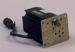
Autopilot Servo

The two most common causes for autopilot induced oscillations are incorrect cable tensions or the A/P servo motor.

During autopilot-engaged flight, oscillations can occur in the roll, pitch or yaw axis. The most commonly squawked oscillation occurs in pitch or often referred to as porpoising. Autopilots (A/P) are designed so that the computer senses the need for correction and then commands a servo motor to drive the control surface via a cable. The drive and speed of the motor, as well as the proper tension of the cable, is determined by design based on the specific characteristics of the aircraft it is installed in.

When troubleshooting autopilot oscillations, the first thing to check is the cable tension of the main or bridle cables. If the cable tension is low the servo will have to "spool" up tension in the cable before it actually moves the control surface to make the correction. This causes a delay in the correction and the autopilot will always be behind, which generates a hunting or oscillation. It often becomes divergent, meaning each cycle of the oscillation gets a little larger in magnitude.

The second most common cause of A/P oscillation is the servo motor itself. If it is getting weak and cannot make the correction in a timely manner, it can cause the same symptoms. When the oscillations are rapid and constant in magnitude, it can be an indication of faulty rate feedback from the servo. This generally is a voltage generated by the servo as it turns providing feedback to the computer so it can adjust command to control the speed of the motor. Faulty or missing feedback causes the servo to run too fast and overshoot, thereby causing a rapid oscillation in the control surfaces.

Duncan Aviation has a team of autopilot technical experts with the expertise and capabilities to work on many aircraft models, including Learjet, Citation, Falcon, Challenger, Hawker, Westwind/Astra, King Air, Piper Cheyenne and Rockwell Commander. Search our aircraft parts and capabilities list to verify our expertise on your autopilot. For more information please call Duncan Aviation's Avionics Customer Account Reps or Technical Representatives.

Take advantage of the Duncan Aviation Radar Promotion and get $100 off of your radar service including functional checks, evaluations, repairs and overhauls.

Larry Troyer serves as an Avionics Tech Rep at Duncan Aviation's Lincoln, Neb. (LNK) facility, specializing in Auto Pilot Systems, Air Data Computers, EFIS, Roll Modules, Mode Couplers and Selectors, Static Inverters, Servos, Spoiler Systems, Cabin Displays and EFD Components. He began his career in aviation in 1982.

Tags: Avionics & Instruments, Troubleshooting

Troubleshooting TFE731 Engine Oil Leaks

Posted by Diane Heiserman on Mon, Nov 28, 2011 @ 11:19 AM

Contributed by Lanny Renshaw, Assistant Manger Turbine Engine Services  

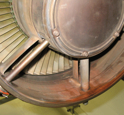
3rd LPT/Exhaust Area

Over-servicing the engine oil level in a TFE731 engine is one cause of oil leaking in the 3rd LPT/Exhaust Area.

There are many reasons that your TFE731 engine may be leaking oil. The hardest part is determining where it is leaking and what to do about it. The following is a list of the most common places you will find oil leaks and their causes.

Oil Leaking from the Breather Pressurizing Valve (BPV)

If there is oil leaking from the BPV after the engine has been shutdown and idle for a day or so, the oil tank may have a cracked internal tube that is allowing oil to flow out of the tank and into the accessory gearbox. When the accessory gearbox is full, the oil will begin to run out the BPV.

If your engine has just come out of its Compressor Zone Inspection (CZI) however, verify that oil pump P/N 3060785-XX is installed. Oil gets trapped in the oil coolers or other areas and moves through the oil pump, filling the accessory gearbox and eventually leaking out of the BPV. This happens on the RH engine installations and sometimes on the #2 position on the F50/900s.

Oil Leaking in the Third LPT/Exhaust Area

If oil begins to pool in the exhaust nozzle area after engine shutdown, the cause may be one of the following:

  1. Over-servicing the engine oil level
  2. Defective #6 carbon seal/rotor
  3. Oil pump P/N 3071949-11 or 3060785-X on RH engine installations allow oil to get trapped in the oil coolers and fill up the #6 bearing area. This oil will eventually run out the #6 carbon seal and down the Third LTP blades. This can be easily fixed with the installation of oil pump P/N 3071949-12, which has a redesigned regulator allowing oil to flow back to the oil tank.

Oil Leaks in the Fan Inlet Area

There are several reasons that oil will leak into the Fan Inlet Area. Here are some of the more common:

  1. #1 carbon seal leaking—oil will be running down the fan blades.
  2. #3 carbon seal leaking— oil will be running out of the Compressor Inlet Stator.
  3. A cut o-ring on the Fan Support Housing or some other areas in or around the Fan Inlet area.

Oil Leaks from the Hot End

If oil is leaking from the hot end, it might be one of the following:

  1. N1 Monopole leaking on the cover plate or the cover plate itself is leaking.
  2. Loose #6 oil pressure and/or scavenge lines.
  3. Oil leak coming from the oil cooler area.

 Duncan Aviation holds service authorizations for Honeywell TFE731-2/-3/-4/-5/20/40/60 Major (MPI) engines at its full-service facilities in Lincoln, NE (LNK), and authorized line services in Battle Creek, MI (BTL). Our TFE731 engine program has been in place since 1980, and we have assembled teams with some of the most talented engine technicians in the industry.

Lanny Renshaw, Assistant Manager of Turbine Engine Services in Lincoln, NE (LNK), manages Duncan Aviation’s modern 20,000-square-foot facility with 12 separate engine bays dedicated to support of the Honeywell TFE731. He started his aviation career in 1982.

Tags: Engine Maintenance, Troubleshooting

TFE731 Engine Oil Pressure Troubleshooting

Posted by Diane Heiserman on Wed, Sep 14, 2011 @ 02:06 PM

Contributed by Lanny Renshaw, Assistant Manager Turbine Engine Services

Breather Pressurizing Valve

When faced with an oil pressure squawk, check the Breather Pressurizing Valve.

Many factors will cause a low or high oil pressure indication on TFE731 engines. One of the more common causes is a faulty Breather Pressurizing Valve (BPV). The following are two scenarios that will lead you to this conclusion.

Oil Pressure Rises During Decent

If the crew reports normal oil pressure at altitude but the pressure rises as the aircraft descends, the most probable cause is the BPV is stuck closed. At sea level, the valve should be open at least .07 in. A defective bellows will cause the valve to be closed on the ground. With a strong light, visually check the BPV. If it is closed, replace the BPV.

Oil Pressure Drops During Climb

Oil pressure that is normal below 27,000 ft but drops as the aircraft climbs higher is another indication the BPV is not closing. Remove the BPV and push on the bellows. They should not move. If you are able to move them, replace the BPV. If the bellows feels normal, swap with the opposite engine. If the squawk is still present, contact your TFE731 Service Center.

TFE731 Engine Oil System Presentation

I will be giving an in-depth presentation on the entire TFE731 Oil System at the Duncan Aviation Intelli-Conference on Sept. 22nd in Teterboro, NJ. My presentation will include additional steps to troubleshoot oil pressure problems, an overview of the oil system schematic and troubleshooting oil leaks. The class is free and attendees will get Inspection Authorization (IA) renewal credit. Register now to reserve your seat!

Duncan Aviation holds service authorizations for Honeywell TFE731-2/-3/-4/-5/20/40/60 Major (MPI) engines at its full-service facilities in Lincoln, NE (LNK), and authorized line services in Battle Creek, MI (BTL). Our TFE731 engine program has been in place since 1980, and we have assembled teams with some of the most talented engine technicians in the industry.

Lanny Renshaw, Assistant Manager of Turbine Engine Services in Lincoln, NE (LNK), manages Duncan Aviation’s modern 20,000-square-foot facility with 12 separate engine bays dedicated to support of the Honeywell TFE731. He started his aviation career in 1982.

Tags: Engine Maintenance, Troubleshooting

get_updates_by_email

Subscribe by Email