banner1.jpg

The Duncan Download Blog: Business Aviation Advice & Observations

Two Most Common Failures of the APS-80 Autopilot System

Posted by Duncan Download Blog on Tue, Jul 15, 2014 @ 09:00 AM

APC---80


Larry  Troyer, Duncan Aviation Avionics Instrument Tech Rep, troublshoots the two most common causes of APS-80 Autopilot System failure. 

The autopilot / flight director system is a complicated system that is common in aircraft from light twins to corporate jets. 

  1. FGC-80- (Flight Director)
  2. APC-80
  3. APA-80

The FGC-80- (Flight Director) processes all lateral/vertical signal inputs depending on the selected mode. It controls the position of the command bars in the Flight Directory Indicator and sends commands to the APC-80. APC-80 receives and processes commands from the Flight Director computer and passes them on to the APA-80, which drives the individual servo motors to control aircraft flight.

Two Most Common Failures

1.   Autopilot intermittently disengages during flight

Most likely cause is the APC or APA. These computers have multiple internal dc power supplies that tend to get out of tolerance or fail completely. They can be temperature sensitive (hot or cold) failing at one specific temperature.

Troubleshooting:

  • If you are able to duplicate the discrepancy on the ground, it is possible to isolate the faulty computer by heating or cooling each box individually.
  • Engage the autopilot on the ground and manually override the controls in pitch or roll. If the autopilot disconnects, the most likely cause is in the APA due to faulty torque monitors.

2.   Autopilot will not engage

Troubleshooting:

When the autopilot won't engage, the APA and APC is still most likely the cause. However because of the extensive internal computer monitoring, there are many other things that could be contributing to the failure. When activating the lever to engage the autopilot, the system automatically initiates a self-test routine. During this self-test a dc voltage is sent to the two NAC-80 accelerometers that in turn generate a fixed signal back to the APA. A correct signal is required to successfully pass the self-test. The NAC-80s also put out a valid flag which is monitored in the APP-80 control head as a condition for engagement.

Other conditions required before the autopilot will engage:

  • Valid vertical gyro
  • Valid from the yaw damper computer
  • Correct part number status on both computers (APA & APC)
  • Continuity thru the yoke disconnect switch

If you have access to a breakout box or logic monitor it helps to isolate the problem down to a box or aircraft problem. Other wise the majority of the times engage problems are caused by either the APC-80 or the APA-80 computers.

More Autopilot Squawk Solutions on the Duncan Download

Troubleshooting Business Aircraft Autopilot: Altitude Hold INOP

Troubleshooting Autopilot-Induced Control Surface Oscillations

3 Things to Look for in a Business Aircraft Autopilot Support Team

Diode Short Can Disengage Learjet 35A Autopilot


Tags: Avionics & Instruments, Squawk Solution, Troubleshooting

Troubleshooting Aircraft Radar Spoking

Posted by Duncan Download Blog on Thu, Mar 20, 2014 @ 01:00 PM

Contributed by Dan Magnus, avionics instruments tech rep

Radar Spoking

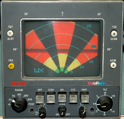
Example indications of spoking.

Spoking is a general term used when a radar system fails. You can determine which part of the system is causing the problem based on what appears on the radar display.

The most common type of spoking is caused by the magnetron or local oscillator. This occurs when they lose lock and do not track with each other. This will typically appear on the radar display as a pie shaped patch and will only be present if there is weather to be shown. This would be a receiver transmitter problem.

Another type of spoking comes from the antenna and is caused by noise from the sweep resolver. This will normally show up on the radar display as a very thin line that will start at the apex of the screen and continue to the edges, no matter which range you are on. This will almost always appear in the same spot on the screen.

Intermittent connections on the antenna can also cause the antenna to pitch up or down causing spikes or humps within the return. This is a common problem for the Primus series of antennas.

Winter Radar Service

Also remember, the winter season is a great time to get your radar unit tested and ready to go prior to spring, when thunderstorms are more prevalent and radar is used most. Take advantage of Duncan Aviation’s Winter Radar Promotion and get $100 off radar servicesincluding functional checks, evaluations, repairs and overhauls through March 31, 2014. To redeem, print and include the $100 rebate with each radar unit shipped.

If you have questions about your radar's operation or how environmental testing will help your radar's reliability, contact Duncan Aviation avionics tech reps.

Dan Magnus is an avionics instrument technical representative located at Duncan Aviation's Lincoln, Neb., location. He specializes in ADF, Comms, Control Heads, CVR, DME Gables Control Heads, Receivers, Nav-Comm/Receivers, Radar Systems, GPS, GNS, Transponders and UNS Components and Systems Specialist. His aviation career began in 1976.

Tags: Avionics & Instruments, Squawk Solution, Troubleshooting

Duncan Aviation Tech Rep Recommendations: Aircraft Radar Operation

Posted by Diane Heiserman on Fri, Mar 07, 2014 @ 02:45 PM

Duncan Aviation

Duncan Aviation radar technicians use the term “Radar Season” to describe the time of year when high winds and instability in the atmosphere whip up severe thunderstorms capable of producing tornadoes. At the beginning of Radar Season, when pilots rely heavily on their radar units to perform perfectly, is when many unexpected squawks may be encountered. 

Below are four Duncan Intelligence articles written by Duncan Aviation's Avionics Tech Reps with tips and recommendations about basic radar operation. 

Radar Operation Tips

The Honeywell ART 2000 and ART 2100 are high-performance modern radar that is proven reliable. But even simple things like getting in a hurry when shutting down the system can have a huge negative impact on operation over time. » Read More 

Radar Antenna Switch Settings

When replacing an ART-2000 or ART-2100 radar receiver transmitter with a loaner or replacement unit, make sure to check that the antenna switch settings are set to the proper flat plate. » Read More

Weather Radar Tilt Management

Storm season is upon us! The technology of radar is a great tool to avoid severe weather, but it is important to remember its limitations. » Read More

Radar Antenna Alignment Procedures

Seven steps to radar antenna alignment (DA-1203A). » Read More

Winter Radar Service

Also remember, the winter season is a great time to get your radar unit tested and ready to go prior to spring, when thunderstorms are more prevalent and radar is used most. Take advantage of Duncan Aviation’s Winter Radar Promotion and get $100 off radar servicesincluding functional checks, evaluations, repairs and overhauls through March 31, 2014. To redeem, print and include the $100 rebate with each radar unit shipped.

If you have questions about your radar's operation or how environmental testing will help your radar's reliability, contact Duncan Aviation avionics tech reps.

Dan Magnus is an avionics instrument technical representative located at Duncan Aviation's Lincoln, Neb., location. He specializes in ADF, Comms, Control Heads, CVR, DME Gables Control Heads, Receivers, Nav-Comm/Receivers, Radar Systems, GPS, GNS, Transponders and UNS Components and Systems Specialist. His aviation career began in 1976.

Adrian Chene serves as an Avionics Tech. Rep. for Duncan Aviation's Battle Creek, Mich. (BTL) facility, specializing in Astra / Westwind, Challenger, Citation, Embraer, Falcon, Gulfstream, Hawker and Learjet aircraft. He began working in aviation in 1996.

Tags: Avionics & Instruments, Troubleshooting

(Video)DGS-65 Directional Gyro: Importance of the Encoder Flex Card

Posted by Diane Heiserman on Thu, Feb 27, 2014 @ 08:31 AM

The DGS 65 Gyro contains a Gyro encoder flex card (flex card) mounted inside the gyro capsule at the top of the internal assembly. This flex card is the information collector for the unit and transmits information to the microprocessor.

There are two sets of LEDs and photo transmitters built into the flex card which must operate properly. By monitoring the sequence in which these transmitters turn on and off, the microprocessor determines the direction that the aircraft’s turn.

In recent years, we have determined that older flex cards are reaching their effective life limits and are now experiencing higher failure rates.

There are two primary ways this unit can fail. First if one or both output channels of the flex card fail, the heading change information will not get to the microprocessor and the unit will no detect heading changes. This will result in a heading freeze on the HSI display. This type of failure may also be intermittent.

Second there is a circuit in the unit which monitors the electric current that is being supplied to the LEDs. If the current is interrupted this monitoring circuit with cause the unit to send a flag signal to the HSI display and the red flag will drop in view.

As with the output channel failure, the heading output will freeze. There is no type of temporary repair, bypass or jumper approved by the OEM and doing so is in violation of FAA regulations.

We recommend following the OEM repair manual procedures for repairing or overhauling the DGS 65 Gyro and only using Rockwell Collins Gyro Encoder Flexcard P/N 6342252001.

Gyro Overhaul

Duncan Aviation is an authorized Rockwell Collins Service Center and is able to overhaul most Rockwell Collins gyroscopes. If you ship your gyro directly to Duncan aviation for overhaul, you could receive your gyro back in 3 to 5 days using Duncan's Aviation's AOG service. When shipping your gyro to Duncan Aviation for overhaul, please follow these critical shipping procedures for a business aircraft gyroscopes.

Duncan Aviation has four avionics tech reps at your service to answer your questions or assist in troubleshooting your avionics units, including the gyro.

Tags: Avionics & Instruments, Troubleshooting, Videos

Don't Ignore Your Aircraft's Radar System During The Winter

Posted by Duncan Download Blog on Mon, Feb 24, 2014 @ 11:23 AM

Contributed by Dan Magnus, avionics instruments tech rep

Aircraft Radar Preventive Maintenance

Typically, the winter months are the time of year that your radar system gets little use. You may be asking yourself, is it necessary for me to run my radar system during the winter season?

Yes!

Our experience at Duncan Aviation has shown that running your radar system during the off season does not shorten its life but may actually extend it and that of the magnetron. There is a higher instance of spoking and intermittent transmitters for customers who have not run their radar systems during the winter months.

We recommend you turn your system on every few weeks over the winter. This simple preventative measure will ensure your radar is functioning properly when you need it and hopefully extend its life.

Winter Radar Service

Also remember, the winter season is a great time to get your radar unit tested and ready to go prior to spring, when thunderstorms are more prevalent and radar is used most. Take advantage of Duncan Aviation’s Winter Radar Promotion and get $100 off radar servicesincluding functional checks, evaluations, repairs and overhauls through March 31, 2014. To redeem, print and include the $100 rebate with each radar unit shipped.

If you have questions about your radar's operation or how environmental testing will help your radar's reliability, contact Duncan Aviation avionics tech reps.

Dan Magnus is an avionics instrument technical representative located at Duncan Aviation's Lincoln, Neb., location. He specializes in ADF, Comms, Control Heads, CVR, DME Gables Control Heads, Receivers, Nav-Comm/Receivers, Radar Systems, GPS, GNS, Transponders and UNS Components and Systems Specialist. His aviation career began in 1976.

Tags: Avionics & Instruments, Troubleshooting

Consequences of Vague Instructions: Sending Aircraft Units for Repair

Posted by Diane Heiserman on Fri, Feb 07, 2014 @ 01:51 PM

Submitted by Jerry Cable, accessories tech rep

describe the image

Avoiding vague or incomplete instructions when sending in aircraft units in for repair and overhaul will save you hours of troubleshooting time and unnecessary expense.

Here. Fix This. 

This reminder may sound obvious, but it is amazing how many accessory units are sent into Duncan Aviation with no explanation or only very little instruction. Within the last year we’ve had a starter generator show up with no paperwork. Is it here for the 2,000 hour overhaul or 1,050 bearing change? What about the actuator with a note that simply said “repair.” Repair what? What is the squawk? When does it occur? 

When this happens we run a function test and hope the results identify the issue. However, this isn’t always a guarantee. Not all squawks can be duplicated on the bench. And many times the problem is related to other aspects of the flight or external conditions and may only fail on the bench when these conditions can be recreated. Taking note of the conditions when the component or system fails, is essential to the effective and timely resolution of the problem.

When removing any units from your aircraft, whether it’s an accessory, avionics, instrument, etc., that is to be sent in for repair or overhaul, always identify the squawk or inspection that needs attention. Having the right information about the circumstances surrounding a squawk can save your tech rep many hours of troubleshooting time and yourself a considerable amount of money.

Duncan Aviation provides accessory unit repairs and overhauls for most popular business aviation airframes. All accessory test equipment is calibrated using NIST certificate traceability. This includes three stab actuator test stands and several sets of test equipment unique to Duncan Aviation.

Jerry Cable is an Accessories Tech Rep located at Duncan Aviation’s Lincoln, Nebr., facility. He is a landing gear and accessory components and systems specialist. His aviation career began in 1991.

Tags: Parts & Accessories, Avionics & Instruments, Aircraft Parts, Troubleshooting

Overhauling NAT (Cobham) Avionics Units

Posted by Diane Heiserman on Thu, Aug 01, 2013 @ 10:59 AM

Dan Magnus, avionics instruments tech rep

NAT avionics overhaul

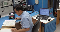
Duncan Aviation avionics technician, Patrick Klein, tests a NAT TH250 tactical communications unit on the bench in front of nine NAT test sets.

Northern Airborne Technology Ltd (NAT), dba Cobham Avionics, designs and produces avionics communications equipment installed aboard helicopters. These units control the audio voice transmissions between the pilot and co-pilot and from the cockpit to the crew/cabin.

One of the more common failures that Duncan Aviation technicians have experienced with these units is intermittent audio squawks. The audio transmitted by these units passes through relays or electronic switches. As relays begin to lose conductivity causing poor contact, intermittent audio is the result. At this point the unit needs to be repaired or overhauled.

If you build it, they will come

Duncan Aviation has full overhaul and repair capabilities on many NAT units. These capabilities are continually growing as customers call and request to send their units to Duncan Aviation for repair or overhaul. If a request comes in and we don’t have a current test set capable of repairing their unit, we build it. And it doesn’t take as long as you might think. We are able to order the manual, build a test set, perform the repair or overhaul AND return the unit to the customer typically quicker than the OEM can do a repair.

Cobham (NAT) repair and overhaul capabilities

Duncan Aviation currently has a total of 12 test sets specifically built to troubleshoot and test hundreds of different Cobham (NAT) models and part numbers. Call a Duncan Aviation avionics tech rep to inquire about our repair and overhaul capabilities for your Cobham (NAT) unit.

Duncan Aviation provides comprehensive avionics and instrument overhaul and repair services, and we are an avionics and instrument authorized service center for more than 50 of the top equipment manufacturers. Our capabilities listings are available online in our inventory and capabilities search.

Dan Magnus is an avionics instrument technical representative located at Duncan Aviation's Lincoln, Neb., location. He specializes in ADF, Comms, Control Heads, CVR, DME Gables Control Heads, Receivers, Nav-Comm/Receivers, Radar Systems, GPS, GNS, Transponders and UNS Components and Systems Specialist. His aviation career began in 1976.

Tags: Avionics & Instruments, Aircraft Parts, Squawk Solution, Troubleshooting, Aircraft Communications

Learjet 20/30 Series: Un-Commanded Aux Cabin Heat

Posted by Diane Heiserman on Wed, May 15, 2013 @ 06:00 AM

Submitted by Dave Schiver, Airframe Tech Rep

This is an update to the Duncan Intelligence article I wrote in December of 2011 about an aging aircraft issue in regards to the Aux Cabin Heat in 20 & 30 Series Learjets not equipped with a Meggitt (formerly known as Keith Products) freon system. This topic was discussed during the NBAA Learjet Technical Committee meeting in February 2012, resulting in Learjet subsequently releasing AFM Temp Rev 2013-01.

Original Duncan Intelligence Article

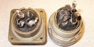
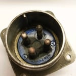
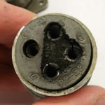
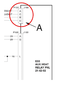
Without a command from the crew, anytime the main ship batteries were turned on, all four of the heating coils in the Aux Cabin Heat system would power on and heat. Upon further investigation, it was discovered that both sides of the P/J-190 connector (ref 21-42-00 in your applicable W/D), that connects the main heating coil power going into the Aux Cabin Heat Relay box, was internally shorted. Both the P- and the J- side were shorted. As a result, anytime the battery charging buss was powered, which is when either Main Ship Battery or Generator is on-line, there was power to the heating coils of the Aux Cabin Heat system.

P/J-190 connectorP/J-190 connectorP/J-190 connector

Internally shorted P/J-190 connector

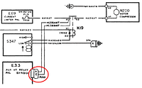
If you check the W/D in regards to the power wires that normally go to the power relays (K17 and K18), you will notice the only protection is a single 150A current limiter (FL3).

Please Note
Since the “P” side is shorted, the heating coils will heat even without the Aux Cabin Heat Relay Panel (E33) installed in the aircraft. With this failure, ALL of the safety features on the control side are ineffective in disabling the heating coils. The only way to remove power from the heating coils is to turn OFF both generators and both main ship batteries. This leaves the Emergency Power Supply (EPS) providing the only electrical power for the aircraft. As per the 35 AFM, aircraft equipped with a single EPS will have electrical power available for approximately 30 minutes in this configuration.

P/J-190 connector wiring diagramP/J-190 connector wiring diagram

P/J-190 connector Wiring Diagram

Dave Schiver is an Airframe Technical Representative at Duncan Aviation’s Lincoln, Nebr. (LNK) facility. He specializes in Learjet aircraft. His aviation career began in 1981.

Tags: Troubleshooting, Learjet

Does AD 2010-07-02 apply to your Honeywell RNZ-850/851?

Posted by Diane Heiserman on Thu, Apr 11, 2013 @ 06:00 AM

Submitted by Scott McKenzie, Avionics Tech Rep

Last summer I wrote an article about the importance of complying with Airworthiness Directive (AD) 2010-07-02 before the deadline of November 3, 2012. This AD is applicable to the Honeywell RNZ-850/851 Integrated Navigation Units (INU) and addresses possible erroneous glide slope or localizer display indications. The deadline has since come and gone, however, at Duncan Aviation we continue to field phone calls from operators who have discovered their AD had been signed off as being complied with, when in fact, it has not. Cessna released CIL-34-02 on March 18, 2013, to address this issue.

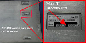
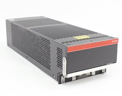
Honeywell RNZ-850/851 Data Plates

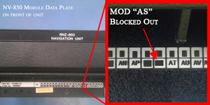
There are two data plates on the Honeywell RNZ-850/851 INU. One is on the front, the other on the bottom. There is confusion about which data plate should be inspected to determine if your unit is in compliance with AD 2010-07-02. The answer is BOTH. Two conditions must be met in order for the unit to be in compliance.

Honeywell RNZ-850/851

Condition #1: Front Data Plate

Closely inspect the mod data plate on the front of the unit. In order to be compliant, the square with the “AS” must be blocked out.
Honeywell RNZ-850/851

Condition #2: Bottom Data Plate

Next inspect the status of the mod data plate on the bottom of the unit. In order to be compliant, the square “T” must be blocked out.

Important Note

Your unit is only in compliance with AD 2010-07-02, when BOTH of these conditions are met.

Duncan Aviation can perform the modification necessary to comply with AD2010-07-02. Contact a Duncan Aviation Avionics Tech Rep for more information.

Avionics Tech Reps

Scott McKenzie is an avionics tech rep located in Duncan Aviation's Lincoln, Nebraska, facility. He specializes in troubleshooting the latest in avionics systems installed on aircraft today. His aviation career began in 1995.

Tags: Avionics & Instruments, Troubleshooting

WOW: An Overlooked Cause of Many Nose Wheel Steering Faults

Posted by Diane Heiserman on Tue, Mar 05, 2013 @ 02:24 PM

Contributed by Jerry Cable, Accessory Tech Rep.

Weight On Wheels

Don't overlook the Weight On Wheel or WOW system when troubleshooting systems faults.

When experiencing an intermittent nose wheel steering fault, the first thought is generally, “what is wrong with the steering servo, computer, valve, actuator or strut?” But don’t overlook a very important part of the system—Weight on Wheels (WOW). This system is very easy to test and replace. It has been my experience that WOW is the cause for more than half of these types of faults.

The WOW System

Most aircraft utilize some type of WOW Sensor or Switch that activates when the aircraft is on the ground. They come in many different sizes shapes and technologies and can be in various positions in the aircraft and landing gear. The one thing they all have in common is they complete the circuitry required to do many other things on the aircraft. From thrust reversers to nose wheel steering and many in between, the aircraft relies on these switches to operate correctly. A faulty or incorrectly adjusted switch/sensor may cause vital systems to not function or function intermittently.

The Wow System

There two basic types: mechanical switches and proximity sensors. Mechanical switches are easier to test; however, they fail more often because they rely on mechanical contacts to create the circuit. Proximity sensors do not utilize a direct mechanical contact but instead use circuitry to decipher when the magnetic field is interrupted. The proximity sensors are more reliable, but more difficult to troubleshoot. Most mechanical switches are either open or closed. Yet due to the circuitry of a proximity sensor it can be partially open and partially closed at the same time. So a proximity sensor that is known to be good but set to an incorrect clearance can cause very erratic behavior of other systems.

Systems that are run through the WOW system are exclusively used either in the air or on the ground, not both. Systems that utilize the WOW system include but not limited to, thrust reversers, nose wheel steering, trim and autopilot.

Jerry Cable is an Accessories Tech Rep located at Duncan Aviation’s Lincoln, Nebr., facility. He is a landing gear and accessory components and systems specialist. His aviation career began in 1991.

Tags: Parts & Accessories, Troubleshooting, Landing Gear

get_updates_by_email

Subscribe by Email