banner1.jpg

The Duncan Download Blog: Business Aviation Advice & Observations

Honeywell RM-855 RMU Upgrade

Posted by Diane Heiserman on Thu, Dec 06, 2012 @ 08:00 AM

Contributed by Scott McKenzie, Avionics Tech Rep

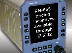
RM-855 Pricing Incentives

Duncan Aviation is able to install new RM-855 units without the the use and expense of an OEM Service Bulletin or STC.

Since 2006, there has been no production or support for the Honeywell RM-850 RMU and replacement parts are extinct. Honeywell is offering the RM-855 as a form, fit and function replacement unit for the discontinued RM-850 RMU. It has been manufactured for several years, and offers greater reliability and functionality.

To upgrade the units, the existing RM-850 connector must be adapted to the new 855. Duncan Aviation is able to install these units without the use and expense of an OEM Service Bulletin or STC. Each unit requires very little labor, and Duncan Aviation's engineering and certification members can approve the modifications through the company's Organization Designation Authorization (ODA). Aircraft downtime is less than a day if parts are ordered in advance.

Affected Aircraft

The following aircraft will most likely have the RM-850 RMUs currently installed:

  • Lear 45
  • Jetstream 41
  • Sikorsky S-76B
  • Global 5000
  • Falcon 2000
  • Hawker 800A / XP
  • Hawker 900XP
  • Hawker 1000
  • Citation 560 Ultra and Excel
  • Citation 650
  • Challenger 601

Duncan Aviation Upgrade Locations

RM-855 upgrades can be performed at any of Duncan Aviation's avionics satellite shops located across the United States. In the case of an RM-850 AOG failure, unit replacement can be performed in the field by an experienced Duncan Aviation avionics technician.

Each installed RM-855 will be covered by a two-year Honeywell warranty, if installed by an Authorized Honeywell dealer.

Scott McKenzie is an avionics tech rep located in Duncan Aviation's Lincoln, Nebraska, facility. He specializes in troubleshooting the latest in avionics systems installed on aircraft today. His aviation career began in 1995.

Tags: Avionics & Instruments, Product Information

Hawker 800XP: Troubleshooting HF Systems Squawks

Posted by Diane Heiserman on Tue, Nov 20, 2012 @ 02:15 PM

Contributed by Scott McKenzie, Avionics Tech Rep

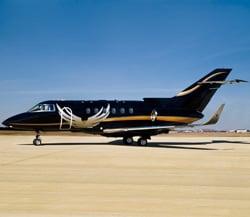
Hawker 800XP

If your Hawker 800XP's HF system is showing signs of intermittent faults, the solution may be as simple as checking for proper bonding at the antenna and antenna coupler.

A Hawker 800XP operator, who was experiencing a squawk on both #1 and #2 HF systems, recently contacted us for support. He was not able to receive transmissions on either system.

Since both systems were exhibiting the same symptoms, the obvious place to begin troubleshooting is by focusing on components that are common between the #1 and #2 HF systems. In this instance: the dual KHF-950 HF system with a shunt antenna. The common components are the KA 162 Dual External Capacitor (or KA 160 Dual Antenna Adapter, if it is a long wire antenna installation) and the HF antenna itself.

Proper Antenna Bonding

The function of the KA 162 Dual External Capacitor is to connect the antenna to the active antenna coupler. Since the HF antenna in this installation is essentially the vertical stabilizer leading edge, the one thing to check with the antenna is proper bonding. Good bonding of the antenna, KAC 952 Power Amplifier/Antenna Coupler and KA 161 External Capacitor or KA 162 Dual Antenna Capacitor is essential for proper operation of the HF system. I cannot count the number of HF squawks that have been remedied by Duncan Aviation avionics technicians simply by going through and cleaning corroded bonding connections at the antenna or antenna coupler.

Tuning faults are also a common squawk for HF systems that have corroded or poor bonding at the antenna or antenna coupler. Bonding at the antenna coupler is done with a bonding strap, and the resistance should not exceed .003 ohms.

So if your aircraft's HF system begins to show signs of intermittent faults, take a few minutes to first check for proper bonding at the antenna and antenna coupler. Many times, this can remedy the problem and save you time and money in the process.

Duncan Aviation is still a Hawker Service Center

In light of the recent changes in the industry for Hawker operators, I want to remind you that Duncan Aviation continues to provide comprehensive Hawker aircraft service and support at all Duncan locations around the world. We are an industry leader in Hawker maintenance, structural repair, landing gear/component overhauls, engine MPIs, avionics upgrades, paint and interior. Our experience and capabilities are second to none.

For more information about Duncan Aviation’s Hawker Services, contact any one of the many Duncan Aviation Hawker experts.

If you have any questions or need assistance when troubleshooting a KHF-950 HF system, contact Duncan Aviation's Avionics Tech Reps, available 24 hours a day, every day.

 Avionics Tech Reps

Scott McKenzie is an avionics tech rep located in Duncan Aviation's Lincoln, Nebraska, facility. He specializes in troubleshooting the latest in avionics systems installed on aircraft today. His aviation career began in 1995.

Tags: Avionics & Instruments, Squawk Solution, Troubleshooting, Hawker

200+ Aviation Acronyms in Celebration of Duncan Download's 200th Post

Posted by Diane Heiserman on Fri, Oct 12, 2012 @ 11:15 AM

Aviation Acronyms

There are nearly 3,000 identified aviation acronyms. Do you know them all?

Each industry has their own set of acronyms and abbreviations that often leave outsiders scratching their heads. There are nearly 3,000 identified aviation acronyms. However, in honor of the Duncan Download’s 200thblog post, I asked our own experts to share 200 aviation-related acronyms that they use most during a normal work day. These overachievers sent me nearly 300.

Do you know them all?

  1. (°C) — Degrees Celsius
  2. (°F) — Degrees Fahrenheit
  3. (A/D) — Analog to Digital Converter
  4. (A/I) — Anti-Icing
  5. (ac) — Alternating Current
  6. (A/C) — Aircraft
  7. (ACO) — Administrative Contracting Officer
  8. (AD) — Airworthiness Directive
  9. (ADC) — Air Data Computer
  10. (ADF) — Automatic Direction Finding
  11. (ADI) — Attitude Indicator
  12. (ADS-B)Automatic Dependent Surveillance - Broadcast
  13. (AES) — Automatic Export System
  14. (AFIS) — Airborne Flight Information System
  15. (AFM) — Aircraft Flight Manual
  16. (AGB) — Accessory Gearbox
  17. (AGC) — Automatic gain control
  18. (AHRS) — Attitude Heading Reference System
  19. (ALI) — Airworthiness Limitation Item
  20. (AMM) — Aircraft Maintenance Manual
  21. (AMS) — Aerospace Material Specification
  22. (ANAC) — Agência Nacional de Aviação Civil
  23. (AOG) — Aircraft on Ground
  24. (APR) — Automatic Power Recovery
  25. (APU) — Auxiliary Power Unit
  26. (ARINC) — Aeronautical Radio Incorporated
  27. (ASAP) — As Soon As Possible
  28. (ASNT) — American Society of Nondestructive testing
  29. (ASSY) — Assembly
  30. (ATA) — Air Transportation Association
  31. (ATC) — Air Traffic Control
  32. (ATIS) — Automatic Terminal Information Service
  33. (ATTCS) — Automatic Take Off Thrust Control System
  34. (BAFO) — Best and Final Offer
  35. (BER) — Beyond economical repair
  36. (BIS) — Bureau of Industry and Security
  37. (BIT) — Binary Digit
  38. (BITE) — Built-in Test Equipment
  39. (BOV) — Bleed-off Valve
  40. (C/P) — Chief Pilot
  41. (C12) — King Air
  42. (C20) — Gulfstream
  43. (C21) — Learjet
  44. (CA) — Certificate of Airworthiness
  45. (CAA) — Civil Aviation Agency
  46. (CAC) — Common Access Card
  47. (CAM) — Certified Aviation Manager
  48. (CAMP) — Computerized Maintenance Program
  49. (CANPASS) — Canadian Passenger Accelerated Service System
  50. (CASP) — Corporate Aircraft Service Program
  51. (CAV) — Commercial Asset Visibility
  52. (CBP) — Customs and Border Patrol
  53. (cc) — Cubic Centimeters
  54. (CCW) — Counterclockwise
  55. (CDP) — Compressor Discharge Pressure
  56. (CDRL) — Contract Data Requirements List
  57. (CDU) — VHF Radio Transceiver
  58. (CFR) — Code of Federal Regulations
  59. (CG) — Center of Gravity
  60. (CIT) — Compressor Inlet Temperature
  61. (CL) — Class
  62. (CLS) — Contractor Logistics Support
  63. (CMR) — Certification Maintenance Requirement
  64. (CMS)Cabin Management System
  65. (COC) — Certificate of Calibration
  66. (Comm) — Communication
  67. (COMSEC) — Communications Security
  68. (CONUS) — Continental United States
  69. (COO) — Country of Origin
  70. (COTR) — Contracting Officer's Technical Representative
  71. (CPAR) — Contractors Performance Assessment Reporting System
  72. (CPCP)Corrosion Prevention Control Program
  73. (CPDLC) — Controller Pilot Data Link Communication
  74. (CPU) — Central Processing Unit
  75. (CRM) — Crew Resource Management
  76. (CRT) — Cathode Ray Tubes
  77. (CSN) — Catalog Sequence Numbers - Cycles Since New
  78. (CVR) — Cockpit Voice Recorder
  79. (CW) — Clockwise
  80. (CZI) — Compressor Zone Inspection
  81. (CZR) — Compressor Zone Repair
  82. (D/A) — Digital to Analogue Converter
  83. (DAR) — Designated Airworthiness Representative
  84. (DCAA) — Defense Contract Audit Agency
  85. (DCMA) — Defense Contracting Management Agency
  86. (DFAR) — Defense Federal Acquisition Regulations
  87. (DFDR) — Digital Flight Data Recorder
  88. (DH) — Decision Height
  89. (DIA) — Diameter
  90. (Dim.) — Dimension
  91. (DME) — Distance Measuring Equipment
  92. (DOD) — Domestic Object Damage
  93. (D.O.D.) — Department of Defense
  94. (DOM) — Director of Maintenance
  95. (DOS) — Department of State
  96. (DPHM) — Diagnostics, Prognostics and Health Management
  97. (DSS) — Defense Security Service
  98. (DUATS) — Direct User Access Terminal Service (weather/flight plan processing)
  99. (e-APIS) — Electronic Advanced Passenger Information System
  100. (EAR) — Export Administration Regulations
  101. (EASA) — European Aviation Safety Agency
  102. (ECCN) — Export Commodity Control Number
  103. (ECS) — Environment Control System
  104. (ECTM) — Engine Condition Trend Monitoring
  105. (EDS) — Engine Diagnostic System
  106. (EDU) — Engine Diagnostic Unit
  107. (EEC) — Electronic Engine Control
  108. (EEI) — Electronic Export Information
  109. (EERM) — Electrically Erasable Read Only Memory
  110. (EFB) — Electronic Flight Bag
  111. (EFD) — Electronic Flight Display
  112. (EFIS) — Electronic Flight Instrument System
  113. (EGWS) — Enhance Ground Proximity Warning System
  114. (EGT) — Exhaust Gas Temperature
  115. (EICAS) — Engine Indication and Crew Alert
  116. (ELT) — Emergency Locator Transmitter
  117. (EPR) — Engine Pressure Ratio
  118. (ESO) — Electronic Sign Off (somewhat unique to Duncan Aviation)
  119. (ESP) — Engine Service Plan
  120. (ET) — Eddy Current Testing
  121. (ETD/(A)/(E) — Estimated Time of Departure/(Arrival)/(Enroute)
  122. (F & C) — Fits and Clearances
  123. (FAA) — Federal Aviation Administration
  124. (FADEC) — Full Authority Digital Electronic Control
  125. (FANS)Future Air Navigation System
  126. (FAR) — Federal Aviation Regulation
  127. (FBO)Fixed Base Operation
  128. (FCPA) — Foreign Corrupt Practices Act
  129. (FCS) — Flight Control System
  130. (FCU) — Fuel Control Unit
  131. (FET) — Federal Excise Tax
  132. (FI) — Flight Idle
  133. (FIR) — Full Indicator Reading
  134. (FIS) — Flight Inspection System
  135. (FMC) — Flight Management Computer
  136. (FMS) — Flight Management System
  137. (FOB) — Fuel On Board
  138. (FOD) — Foreign Object Damage
  139. (FSDO) — Flight Standards District Office
  140. (FSO) — Facility Security Officer
  141. (FSOV) — Fuel Shut-off Valve
  142. (FT) — Function Test
  143. (FTR) — Federal Trade Regulations
  144. (FWD) — Forward
  145. (GBS) — Ground Based Software
  146. (GEAE) — GE Aircraft Engines
  147. (GFP) — Government Furnished Property
  148. (GI) — Ground Idle
  149. (GND) — Ground
  150. (GOM) — General Operations Manual
  151. (GPS) — Global Positioning System
  152. (GPWS) — Ground Proximity Warning System
  153. (H/W) — Hardware
  154. (HIRL) — High Intensity Runway Lighting
  155. (HP) — High Pressure
  156. (HPT) — High Pressure Turbine
  157. (HR.) — Hour
  158. (HSD)High Speed Data
  159. (HSI) — Hot Section Inspection
  160. (HSI)Horizontal Situation Indicator
  161. (HSR) — Hot Section Refurbishment
  162. (HTS) — Harmonized Tariff System
  163. (Hz) — Hertz
  164. (I) — Incident
  165. (IAW) — In Accordance With
  166. (ICA) — Instructions for Continued Airworthiness
  167. (ICAO) — International Civil Aviation Organization
  168. (ID) — Inside Diameter
  169. (IDG) — Integrated Drive Generator
  170. (IETM) — Interactive Engine Technical Manual
  171. (IFR) — Instrument Flight Rules
  172. (IGV) — Inlet Guide Vane
  173. (ILS) — Instrument Landing System
  174. (in.) — Inch
  175. (INBD) — Inboard
  176. (IPC) — Illustrated Parts Catalog
  177. (ISO) — International Standards Organization
  178. (ITAR)International Traffic and Arms Regulations
  179. (ITT) — Interturbine Temperature
  180. (JAR OPS) — Joint Aviation Requirement for Operation (Europe)
  181. (JPAS) — Joint Personnel Adjudication System
  182. (JTR) — Joint Travel Regulations
  183. (kg.) — Kilogram
  184. (kPa) — Kilopascals
  185. (L/HIRF) — Lightning/High Intensity Radiated Field
  186. (lb.) — Pound
  187. (LOI) — Letter of Intent
  188. (LPT) — Low Pressure Turbine
  189. (LPV)Localizer Performance with Vertical guidance
  190. (LRM) — Line Replaceable Module
  191. (LRU) — Line Replaceable Unit
  192. (M/N) — Model Number
  193. (Max) — Maximum
  194. (MDA) — Minimum Descent Altitude
  195. (MEL) — Minimum Equipment List
  196. (MFC) — Main Fuel Control
  197. (MFD) — Multi-Function Display
  198. (Min) — Minimum
  199. (MLG) — Main Landing Gear
  200. (MM) — Maintenance Manual
  201. (MOA) — Military Operations Area
  202. (MPA) — Maximum Power Assurance
  203. (MPD) — Maintenance Planning Document
  204. (MPI)Major Periodic Inspection
  205. (MPU) — Multifunction Processor Unit
  206. (MRA) — Major Repair/Alteration
  207. (MRB-R) — Maintenance Review Board Report
  208. (MSG-3) — Maintenance Steering Group 3rd Task Force Aircraft Maintenance Program
  209. (MSP) — Maintenance Service Plan
  210. (MT) — Magnetic Particle Testing
  211. (MU) — Measurement Uncertainty
  212. (MUR) — Measurement Uncertainty Ratio
  213. (N2 -) — Nitrogen
  214. (NAA) — National Aviation Agency
  215. (NATO) — North Atlantic Treaty Organization
  216. (NAV) — Navigation
  217. (NBAA) — National Business Aviation Association
  218. (NDB) — Non-Directional Beacon
  219. (NDT) — Non-Destructive Testing
  220. (NextGen)Next Generation Air Transportation System
  221. (NFF) — No Fault Found
  222. (NICAD) — Nickel Cadmium
  223. (NIST) — National Institute of Standards & Technology
  224. (NLG) — Nose landing gear
  225. (NOTAM) — Notice to Airmen
  226. (O2) — Oxygen
  227. (OC) — On condition
  228. (OCONUS) — Outside Continental United States
  229. (ODA)Organization Delegation Authorization
  230. (OH) — Overhaul
  231. (OIML) — International Organization for Legal Metrology
  232. (OOT) — Out of Tolerance
  233. (OUTBD) — Outboard
  234. (P/N) — Part Number
  235. (PAMA) — Professional Aviation Maintenance Association
  236. (PAR) — Previous Authorization Required
  237. (PCO) — Procuring Contracting Officer
  238. (PIC) — Pilot In Command
  239. (PIREP) — Pilot Reports
  240. (PM) — Program Manager
  241. (PMA)Parts Manufacturer Approval
  242. (POA) — Power of Attorney
  243. (PSE) — Primary Structural Element
  244. (PSU) — Passenger service unit
  245. (PT) — Penetrant testing
  246. (PWS) — Performance Work Statement
  247. (QA) — Quality Assurance 
  248. (QAR) — Quality Assurance Representative
  249. (QCM) — Quality Control Manual
  250. (QT) — Quick Turn
  251. (RAAS) — Runway Awareness and Advisory System
  252. (RAD) — ALT Radio Altimeter
  253. (RAT) — Ram Air Turbine
  254. (RFI) — Request for Information
  255. (RFM) — Removed From Market
  256. (RFQ)Request for Quote
  257. (RNAV) — Area Navigation
  258. (RNP) — Required Navigation Performance
  259. (ROM) — Rough order of magnitude
  260. (RSGOM) — Repair Station General Operating Manual
  261. (RSM) — Repair Station Manual
  262. (RTS) — Return To Service
  263. (RTU) — Radio Tuning Unit
  264. (RVSM)Reduced Vertical Separation Minimums
  265. (S/N) — Serial Number
  266. (SATCOM)Satellite Communications
  267. (SB) — Service Bulletin
  268. (SBB)Swiftbroadband
  269. (SELCAL) — Selective Calling
  270. (SHOT) — Since Hot Section Overhaul
  271. (SIC) — Second In Command
  272. (SMOH) — Since Major Overhaul (Engines)
  273. (SMS) — Safety Management System
  274. (SOP) — Standard Operating Procedure
  275. (SOW) — Statement of Work
  276. (STC)Supplemental Type Certificate
  277. (TAF) — Terminal Area Forecast
  278. (TAP) — Total Assurance Program
  279. (TAR) — Test Accuracy Ratio
  280. (TAWS) — Terrain Awareness Warning System
  281. (TBO) — Time Between Overhaul
  282. (TCAS) — Traffic Collision Avoidance System
  283. (TCAS MOPS 7.1) — Minimum Operation Performance Specification 7.1
  284. (TCH) — Threshold Crossing Height
  285. (TFR) — Temporary Flight Restriction
  286. (TSA) — Transportation Security Administration
  287. (TSH) — Time Since Hot (Engines)
  288. (TSN) — Time Since New
  289. (TSO) — Time Since Overhaul
  290. (TTSN) — Total Time Since New
  291. (TUR) — Test Uncertainty Ratio
  292. (UC) — Under Contract
  293. (USCG) — United States Coast Guard
  294. (UT) — Ultrasonic Testing
  295. (VFR) — Visual Flight Rules
  296. (VSI) — Vertical Speed Indicator
  297. (WAAS)Wide Area Augmentation System
  298. (Wi-Fi) — Wireless Fidelity

Duncan Aviation is an aircraft service provider supporting the aviation needs of government and business operators and other service providers. Services include major and minor airframe inspections, engine maintenance, major retrofits for cabin and cockpit systems, full paint, interior and modification services and pre-owned aircraft sales and acquisitions. Duncan Aviation also has aircraft components and parts solutions experts available 24/7/365 at 800.228.1836 or 402.475.4125 (international) who can handle any aircraft system problem with immediate exchanges, rotables, loaners or avionics/instrument/accessory/propeller repairs and overhauls.

Complete service facilities are located in Lincoln, Nebraska, and Battle Creek, Michigan. Additional locations include a maintenance facility in Provo, Utah, more than 20 satellite avionics facilities and eight engine Rapid Response Team launch offices strategically located for worldwide support.   

For more information about any of Duncan Aviation’s services, contact us at 402.475.2611 or 800.228.4277. Or visit us on the web at www.DuncanAviation.aero.

Tags: Avionics & Instruments, Aircraft Parts, Avionics Installation, Engine Maintenance, Airframe Maintenance, Announcements, AOG

Squawk Solution: Proper Operation of the KHF-950 HF System

Posted by Diane Heiserman on Thu, Sep 27, 2012 @ 01:00 PM

Contributed by Scott McKenzie, Avionics Tech Rep

At Duncan Aviation, we recently have had a number of components sent in for a KHF-950 HF system, with a KFS-594 Miniature Control Unit installed, that have been squawked as being stuck in transmit mode or the frequency is changing on the controller every time a transmit is attempted. After bench testing, it was determined that there were no faults with the suspected units, but a misunderstanding of the proper operation of this system. 

Here’s a quick refresher course.

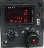
Direct Frequency Mode

figure 1. Direct Frequency Mode.

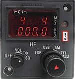
Channel Mode

figure 2. Channel Mode.

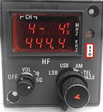
Program Mode

figure 3. Program Mode.

Direct Frequency Mode

The first thing that technicians should do when testing the KHF-950 HF system is select channel 0 (direct frequency mode) on the HF controller and enter the desired frequency.  (figure 1. Direct Frequency Mode)

This ensures the frequency that is selected via the controller is the frequency that will be both received and transmitted (simplex operation) on when the microphone is keyed. If any other channel is selected (1 through 19), it is possible that the frequency displayed on the controller will change when attempting to transmit. 

 Channel Mode

By selecting a channel (1 through 19), the user can store preset frequencies using the white STO button. To program a preset channel frequency, first select the channel. Next, enter the desired frequency and press the STO button. (figure 2. Channel Mode)

Program Mode

Each channel can also be programmed for duplex operation. Duplex operation is receiving on one frequency, while transmitting on a different frequency. To program a channel for duplex operation, first select the desired channel, then enter the desired receive frequency and press the STO button. The display on the control should now be in program mode. Program mode is annunciated by a flashing dash in the space adjacent to the channel number. (figure 3. Program Mode photo)

Also note that the TX annunciation is in the upper right hand corner. You may now enter the desired transmit frequency, and press the STO button again. The selected channel is now programmed for duplex operation.

STO Button

The STO button can perform a couple of other functions in addition to being used to store preset frequencies. If the STO button pressed while the microphone is keyed, a 1000Hz tone will be transmitted. This is used to break the squelch of some stations. 

Also, pressing the STO button will clear any error conditions, which are annunciated by a flashing "E" being displayed for more than three seconds. If the display shows a TX annunciation upon power up, and you are not able to control the cursor, pressing the STO button three times should clear this indication and allow for full function of the HF controller.

If you have any questions or need assistance when troubleshooting a KHF-950 HF system, contact Duncan Aviation's Avionics Tech Reps, available 24 hours a day, every day.

 Avionics Tech Reps

Scott McKenzie is an avionics tech rep located in Duncan Aviation's Lincoln, Nebraska, facility. He specializes in troubleshooting the latest in avionics systems installed on aircraft today. His aviation career began in 1995.

Tags: Avionics & Instruments, Squawk Solution, Troubleshooting

Honeywell RNZ-850/851 Avionics AD Deadline Approaching

Posted by Diane Heiserman on Tue, Sep 25, 2012 @ 09:00 AM

Contributed by Scott McKenzie, Avionics Tech Rep

The date for complying with Airworthiness Directive (AD) 2010-07-02 is rapidly approaching. November 3, 2012 is the date that operators are required to be in compliance of this AD. The AD is applicable to Honeywell RNZ-850/851 Integrated Navigation Units and addresses possible erroneous glide slope or localizer display indications.

Does this AD apply to you?

Verifying applicability is a simple two-step process.

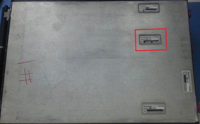
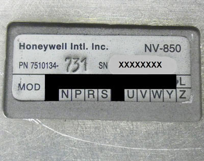
NV-850 module data plateStep 1 NV-850 module data tag mod status Step 2
  1. Check the NV-850 module data plate on the bottom of the RNZ-850/851 Integrated Navigation Unit. This AD is only applicable to units with NV-850 modules with the following part numbers: 7510134-611, -631, -701, -731, -811, -831, -901 or -931.
  2. If you have a unit installed with one of the above part numbers, check the mod status on the bottom of the data tag. If the unit has block “T” blackened out, then the unit IS in compliance of AD2010-07-02. If the unit does not have mod “T” installed, then the unit requires modification to comply with this AD.

Don’t wait until the last minute to take care of this AD. Demand for this modification will only get higher. The longer you wait to comply, the longer you may wait to get your unit back. Duncan Aviation is able to perform the modification necessary to comply with AD2010-07-02. Contact a Duncan Aviation Avionics Tech Rep for more information.

Avionics Tech Reps

Scott McKenzie is an avionics tech rep located in Duncan Aviation's Lincoln, Nebraska, facility. He specializes in troubleshooting the latest in avionics systems installed on aircraft today. His aviation career began in 1995.

Tags: Avionics & Instruments, Troubleshooting

The Trouble With Troubleshooting Avionics Squawks

Posted by Diane Heiserman on Tue, Jun 26, 2012 @ 08:00 AM

Contributed by Curt Campbell, Avionics Tech Rep

Chain of communication

Long chains of communication are notorious for 'losing' pertinent information about a squawk.

Remember the “telephone” game when you were a kid? The game where a specific sentence or phrase was whispered to the first person in line and they in turn whispered it to the next and the next, until it got to the last person? Most of the time what the last person heard is nowhere near the original phrase.

Although we may be grown up, we still have similar issues with long chains of communication. In my experience as an Avionics Tech Rep, unless I am talking to the person who witnessed the squawk, I go under the assumption that there is always more to the story than what I am told. Or in some cases, a completely different story altogether.

During a squawk event, the first opportunity for ‘lost’ salient information is with the flight crew. They are tasked with the verbalization of the squawk, and in an effort to be concise, may inadvertently leave out valuable clues that will help pinpoint the cause of the event. They may also be unaware of additional checks or other observations that can aid in troubleshooting. Of course every time the crew’s information is passed on to the Director of Maintenance (DOM), MRO or avionics tech rep, the verbiage is subtlety changed based on the perceptions of each individual, resulting in what in some cases is a completely different squawk than what was originally witnessed. This results in misdiagnosis, expensive parts needlessly changed and lengthy intervals to finally diagnose and clear the discrepancy.

How can you avoid this wasted time and extra expense? Here are some simple tips that can save you in the long-run.

Eliminate the Middleman

llow the person or team charged with resolution of the issue direct access to the crew member who witnessed the issue. Don’t assume you know what the crew saw. Their perceptions may be different than yours

Use That Smartphone as a Troubleshooting Aid

If the issue is visual, take a video of the failure. This is particularly helpful for flight control system problems, which can be difficult to describe accurately. In the case of the flight control system, try to capture the primary flight instruments as well as the yoke movements in the video. 

Educate Your Crew

Make sure the crew understands common troubleshooting steps for the specific systems installed in your aircraft. For instance, I often find the crew will observe a flight control system issue at cruise with altitude hold and GPS modes selected, but will not try other modes such as HDG and Pitch hold. Testing these modes at the time the squawk occurs would significantly reduce the required troubleshooting and/or unnecessary parts procurement.

Intermittent & Ongoing Squawks

Send the crew off with a checklist of things to accomplish when the issue occurs. Conditions such as altitude, airspeed, temperature, weather conditions, can all play a roll in determination of the issue.

Call Your MRO Inflight

I’ve participated in ‘live troubleshooting’ calls many times and it works. They can ask questions in real-time, often resulting in quicker diagnosis and faster repair.

Duncan Aviation has twenty Technical Representatives, available 24 hours a day, seven days a week, to troubleshoot and answer questions about every aircraft, engine and avionics system in a business aircraft. They are proactive in their education, taking the necessary steps to stay current on the latest technologies. They spend hours researching the latest Airworthiness Directives (AD), Service Bulletins (SB) and Service Letters (SL) released by the Original Equipment Manufacturers (OEMs) and impart that knowledge to technicians and customers.

Curt Campbell is a Duncan Aviation Avionics Tech Rep. located in Lincoln, NE, specializing in troubleshooting squawks and offering tech support for business aircraft avionics. Curt's aviation career began in 1975.
Tags: Avionics & Instruments, Troubleshooting

RVSM Monitoring Requirement

Posted by Diane Heiserman on Thu, Jun 21, 2012 @ 02:04 PM

Contributed by Randy Dill, RVSM GMU Flight Monitor

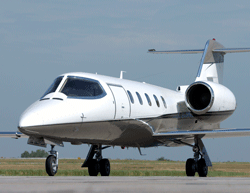
Learjet 35

Most Learjet 35 models are not Mode S and require the RVSM minimum monitoring.

In a FAA Reduced Vertical Separation Minimum (RVSM) Notam dated March 9, 2011, aircraft of operators authorized to use RVSM airspace must conduct monitoring every two years or within 1,000 flight hours per aircraft, whichever period is longer. This requirement is a follow-up to the RVSM regulation implemented on January 20, 2005, in the United States and parts of Canada and Mexico. It became applicable on May 18, 2011, and operators have until November 18, 2012, to comply.

The majority of aircraft that fly in RVSM airspace, Flight Level 290 through Flight Level 410, must meet RVSM minimum monitoring requirements, meaning aircraft that fly within that airspace will be separated by a distance of 1,000 feet. To accomplish this, aircraft are monitored to ensure the equipment on the aircraft (FMS, autopilot, etc.), keep the aircraft at their respective assigned altitudes.

RVSM Monitoring Methods

If the aircraft is Mode S, it can fly over ground-based stations (AGHME) and have their altitude recorded and then published to the FAA RVSM website. There is no cost to the operator for this method of monitoring; however, they will not receive any form of documentation of the results.

Mode C aircraft, or Mode S if the operator prefers, must be monitored by a qualified technician using a GMU (GPS-Based Monitoring Unit) while aboard the aircraft. They track the altitude for a minimum of 30 minutes while flying at altitude. Both the customer and their local FAA representatives receive physical data from these flights, as well as the results being published on the FAA website.

Duncan Aviation has been monitoring RVSM aircraft since 2004. Many of the aircraft we’ve monitored are now due to be retested before the November deadline. More information on regulatory Requirements for RVSM Maintenance is available in the Duncan Aviation Intelligence Newsletter

For more information about scheduling your aircraft RVSM Flight Monitoring, contact:

Battle Creek, Michigan (BTL)

Lincoln, Nebraska (LNK)

Randy Dill is a qualified RVSM GMU Flight Monitor and a CNC Fabrications Specialist at Duncan Aviation's Lincoln, Neb., facility. He specializes in manufacturing custom aircraft parts. His aviation career began in 1986.

Tags: RVSM, Avionics & Instruments, Avionics Installation

Troubleshooting Business Aircraft Autopilot: Altitude Hold INOP

Posted by Diane Heiserman on Tue, Mar 27, 2012 @ 12:15 PM

Contributed by Avionics Tech Reps Curt Campbell and Larry Troyer

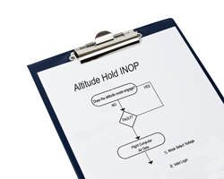
Autopilot INOP

Asking the right questions at the right time, will lead you in the right direction towards a solution when troubleshooting an autopilot squawk.

Figuring out the cause of an autopilot (A/P) squawk is more involved than just looking up the symptoms and determining a course of action. It involves a rather complicated decision tree that includes several steps and scenarios. Altitude Hold INOP is a common A/P squawk that we encounter nearly every day. Below are some of the basic questions we ask that lead us in the right direction towards a correct solution.

Does the Altitude Mode show engaged?

If the altitude mode does not show engaged, the next step is to determine if the fault lies with the flight computer or air data. There are two main things required by the Flight Director (FD) computer in order for the Altitude Hold Mode to engage: 1) Mode Select voltage, and 2) Valid logic from the Air Data Sensor. If both signals are being transmited correctly to the FD computer, you can assume the FD computer is faulty.  

Does the A/P drift off altitude?

If the A/P is drifting off altitude, first determine of the flight command bars are responding appropriately. For instance, if the A/P drifts off the altitude and the flight command bars do not recognize it and give the command to correct, the altitude error from the Air Data Sensor is not getting to the flight computer. This could be a faulty Air Data Sensor or FD computer. If the error can be confirmed as having reached the FD computer, then the computer is faulty.

However, if the flight command bars respond with corrective action when the A/P drifts off but the A/P doesn’t respond, I would took into the A/P amp or its connection to the FD computer. Another thing would be to check the Auto Trim. If the Auto Trim does not come in and take the effort away from the elevator servo after initial correction, the servo may run out of authority to hold the correction and allow the aircraft to drift off.

Does the A/P “hunt” for the altitude?

If the A/P hunts for the altitude, this could indicate either an altitude hold or pitch channel problem. Even though it may appear to be only an altitude hold failure, we need to remember in altitude hold, the A/P is trying to hold a tight reference of altitude against pitch attitude input. A pitch failure could be caused by any number of other parameters that will appear more often during altitude hold, due to the tight reference.

As you can see, there is no obvious answer to an Autopilot Altitude Hold INOP squawk and these questions are not all-inclusive. We haven’t addressed cable tensions or servo motors. When troubleshooting Auto Pilot squawks, don’t be discouraged if the answer isn’t obvious.

Lear more about Basic Autopilot Troubleshooting from Curt and Larry as they present at the 55th Annual AEA International Convention and Trade Show in Washington, D.C., from April 3-6, 2012.

Curt Campbell and Larry Troyer are Duncan Aviation Avionics Tech Reps. located in Lincoln, NE, specializing in troubleshooting squawks and offering tech support for business aircraft avionics. Curt's aviation career began in 1975. Larry's aviation career began in 1982. 


Tags: Avionics & Instruments, Squawk Solution

Troubleshooting Autopilot-Induced Control Surface Oscillations

Posted by Diane Heiserman on Mon, Feb 06, 2012 @ 01:10 PM

Contributed by Larry Troyer, Avionics Tech Rep

Autopilot Servo

The two most common causes for autopilot induced oscillations are incorrect cable tensions or the A/P servo motor.

During autopilot-engaged flight, oscillations can occur in the roll, pitch or yaw axis. The most commonly squawked oscillation occurs in pitch or often referred to as porpoising. Autopilots (A/P) are designed so that the computer senses the need for correction and then commands a servo motor to drive the control surface via a cable. The drive and speed of the motor, as well as the proper tension of the cable, is determined by design based on the specific characteristics of the aircraft it is installed in.

When troubleshooting autopilot oscillations, the first thing to check is the cable tension of the main or bridle cables. If the cable tension is low the servo will have to "spool" up tension in the cable before it actually moves the control surface to make the correction. This causes a delay in the correction and the autopilot will always be behind, which generates a hunting or oscillation. It often becomes divergent, meaning each cycle of the oscillation gets a little larger in magnitude.

The second most common cause of A/P oscillation is the servo motor itself. If it is getting weak and cannot make the correction in a timely manner, it can cause the same symptoms. When the oscillations are rapid and constant in magnitude, it can be an indication of faulty rate feedback from the servo. This generally is a voltage generated by the servo as it turns providing feedback to the computer so it can adjust command to control the speed of the motor. Faulty or missing feedback causes the servo to run too fast and overshoot, thereby causing a rapid oscillation in the control surfaces.

Duncan Aviation has a team of autopilot technical experts with the expertise and capabilities to work on many aircraft models, including Learjet, Citation, Falcon, Challenger, Hawker, Westwind/Astra, King Air, Piper Cheyenne and Rockwell Commander. Search our aircraft parts and capabilities list to verify our expertise on your autopilot. For more information please call Duncan Aviation's Avionics Customer Account Reps or Technical Representatives.

Take advantage of the Duncan Aviation Radar Promotion and get $100 off of your radar service including functional checks, evaluations, repairs and overhauls.

Larry Troyer serves as an Avionics Tech Rep at Duncan Aviation's Lincoln, Neb. (LNK) facility, specializing in Auto Pilot Systems, Air Data Computers, EFIS, Roll Modules, Mode Couplers and Selectors, Static Inverters, Servos, Spoiler Systems, Cabin Displays and EFD Components. He began his career in aviation in 1982.

Tags: Avionics & Instruments, Troubleshooting

Citation 560XL/XLS: Keeping Avionics Online During Engine Startup

Posted by Diane Heiserman on Tue, Jan 17, 2012 @ 10:30 AM

Contributed by Chuck Zahnow, Airframe Tech Rep

The normal engine startup sequence for Citation 560XL aircraft removes power from the avionics system, causing it to drop offline. The reason for this is the avionics are isolated from the start system. SB560XL-24-14R2 allows the avionics to stay online by using the APU generator during engine start.

This service bulletin (SB) is a really great modification for the airplane, but there are still aircraft that have not been modified and time is running out. Cessna warranty covers all affected aircraft until February 2012. If the SB has not been accomplished yet, it is not too late.

The modification requires removal of the aft J-box and access to the aft baggage floor and cockpit PCB box. The best option for this to be done is at a major inspection, since it won’t add downtime and the inspection improves access to these areas. If the SB is done alone, it will take about one week.

If there is not a major inspection to be done prior to February, that is not an issue. We have been able to get this done and get it covered by warranty, including the hours of access.

Affected serial numbers include:

  • 560XL: 5002-5372 (if APU is installed)
  • 560XLS: 5501-5799 (all)

If your aircraft is affected and you haven’t done this SB, I strongly recommend you get it done before the warranty expires.

Duncan Aviation is a Cessna authorized service center for Citation 500 and 600 series. For a list of our Citation service capabilities, technical support and service sales contacts, please visit www.DuncanAviation.aero/airframe/citation.php.

Chuck Zahnow serves as an Airframe Technical Representative at Duncan Aviation’s Battle Creek, Mich. (BTL) facility, specializing in Citation and Hawker aircraft. He began his career in aviation in 1996.

Tags: Avionics & Instruments, Avionics Installation, Engine Maintenance, Airframe Maintenance

get_updates_by_email

Subscribe by Email